Introduction
The purpose of this exercise is to create separate VLANs for different groups of users in each building. In a later exercise we will configure the core router so that each VLAN is using a different IP subnet.
This lab is a continuation from the Spanning Tree exercise and the lab setup is identical:

Accessing the Lab
Here is a reminder of how to access the lab. Refer to the correct document below for information about logging into the devices that have been assigned to you:
VIRTUAL ENVIRONMENT: Virtual Environment Lab Access Instructions
PHYSICAL HARDWARE: Physical Hardware Lab Access Instructions
VLANs
We now want to segment the network to separate network management traffic from end-user traffic (staff and students). Running one large flat network across the entire campus simply does not scale as was covered during the presentation. Each of these segments will be a separate subnet.
We need to take a structured approach with this migration. While we have the luxury of working in a lab for this workshop, on a campus network migration from a flat to a routed backbone needs care and planning.
The process will be this:
- Create a VLAN for the Staff (called STAFF)
- Create a VLAN for the Students (called STUDENT)
- Create a VLAN for device management (called MGMT)
- Shut down VLAN1 – VLAN1 is the Cisco default, has many well documented security risks for campus networks, and should never be used.
VLANs and Address Plan
We will now create the VLANs described in the previous steps. As each VLAN is a different network, they need their own address subnet (IPv4 and IPv6). The Campus Core switch will route between each VLAN (so called L3-switch: an ethernet switch which has some L3 routing capability).
| Name | VLAN | IPv4 | IPv6 |
|---|---|---|---|
| Building 1 Management | 10 | 172.2X.10.0/24 | 2001:DB8:X:10::/64 |
| Building 1 Staff | 11 | 172.2X.11.0/24 | 2001:DB8:X:11::/64 |
| Building 1 Student | 12 | 172.2X.12.0/24 | 2001:DB8:X:12::/64 |
| Building 2 Management | 20 | 172.2X.20.0/24 | 2001:DB8:X:20::/64 |
| Building 2 Staff | 21 | 172.2X.21.0/24 | 2001:DB8:X:21::/64 |
| Building 2 Student | 22 | 172.2X.22.0/24 | 2001:DB8:X:22::/64 |
These IP addresses are also documented in the master IP address plan.
These two tables show the IP addresses which are assigned to the management interfaces of the core, distribution and edge switches. Replace the X and N in the configuration examples below with the appropriate numbers from these tables:
| Building 1 Management | VLAN | IPv4 | IPv6 |
|---|---|---|---|
| core1.campusX | 10 | 172.2X.10.1/24 | 2001:DB8:X:10::1/64 |
| dist1-b1.campusX | 10 | 172.2X.10.2/24 | 2001:DB8:X:10::2/64 |
| edge1-b1.campusX | 10 | 172.2X.10.3/24 | 2001:DB8:X:10::3/64 |
| edge2-b1.campusX | 10 | 172.2X.10.4/24 | 2001:DB8:X:10::4/64 |
| Building 2 Management | VLAN | IPv4 | IPv6 |
|---|---|---|---|
| core1.campusX | 20 | 172.2X.20.1/24 | 2001:DB8:X:20::1/64 |
| dist1-b2.campusX | 20 | 172.2X.20.2/24 | 2001:DB8:X:20::2/64 |
| edge1-b2.campusX | 20 | 172.2X.20.3/24 | 2001:DB8:X:20::3/64 |
| edge2-b2.campusX | 20 | 172.2X.20.4/24 | 2001:DB8:X:20::4/64 |
Disabling VTP
VTP (VLAN Trunking Protocol) is a proprietary Cisco technology that allows for dynamic VLAN provisioning. We will not use it here.
Disable VTP entirely:
vtp mode off(On older switches without vtp mode off, use vtp mode transparent instead)
Configure the switches with MGMT, STAFF and STUDENT VLANs.
Add the VLANs to the VLAN database on each switch and give them names to better identify them. If you don’t do this, the switches won’t know which VLANs are present in the network.
On the Core Switch:
vlan 10
 name MGMT1
vlan 11
 name STAFF1
vlan 12
 name STUDENT1
vlan 20
 name MGMT2
vlan 21
 name STAFF2
vlan 22
 name STUDENT2
On Building 1 switches:
vlan 10
 name MGMT1
vlan 11
 name STAFF1
vlan 12
 name STUDENT1
On Building 2 switches:
vlan 20
 name MGMT2
vlan 21
 name STAFF2
vlan 22
 name STUDENT2
Check STP for each VLAN
Verify the Spanning Tree status:
show spanning-tree mstYou should see:
##### MST0 vlans mapped: 1-4094This means that all VLANs are being protected by the same spanning tree instance (MST0), and hence no additional configuration is required.
Configure trunk ports
The Core switch connects to the Distribution switches in each building, which in turn connect to two Edge switches in each building. So that we can pass VLAN tags from switch to switch, we need to convert the interfaces which connect between the switches to trunk ports using 802.1Q encapsulation. (The Cisco default is for the interfaces to pass ethernet frames untagged.)
802.1Q
To set 802.1Q encapsulation on an interface (the default on most switches today1), the command used under the interface setting is switchport trunk encapsulation dot1q.
Trunk
All switch ports are configured as access ports by default, so we need to convert the chosen port to a trunk port – to do this we use switchport mode trunk under the interface configuration.
Limiting VLANs on Trunks
By default the switches will send all configured VLANs on all trunk interfaces. This will not scale for a large network, so we need to specifically list which VLANs are allowed on which trunks.
For example, the Core Switch should only allow VLANs 10, 11 and 12 towards Distribution Switch in Building 1. So we need to indicate on the interface which VLANs will be sent on the trunk port. For Building 1, the command we use is switchport trunk allowed vlan 10-12. And VLANs 20, 21 and 22 towards Distribution Switch in Building 2 – the command for those switches in Building 2 is switchport trunk allowed vlan 20-22.
Configuration Example
Combining all the trunk settings we required, here is an example, on Distribution switch in Building1 in Campus1:
interface GigabitEthernet 1/0
 description Trunk Link to edge1-b1.campus1
 switchport trunk encapsulation dot1q
 switchport mode trunk
 switchport trunk allowed vlan 10-12
 load-interval 30
!Reminder: Check the diagram to see which ports you need to modify – don’t just guess! Note that there are two links between the distribution and edge1 switch in each Building.
And don’t forget to put the descriptions on the interfaces and modify the default load interface from 5 minutes to 30 seconds!
IP Addressing for the MGMT VLAN
We originally configured the switches so that we were using VLAN 1 to manage them (and provide end user access for the whole campus!). And the IPv4 address block we have used up to now was the entire 172.2X.0.0/16 (for IPv6 we only used 2001:DB8:X:0::/64) as we had one large broadcast domain for the whole campus.
We need to move away from this now.
We cannot simply address the VLANs we created using a subnet of 172.2X.0.0/16 while that entire address block is being used for VLAN 1 – Cisco IOS does not allow overlapping subnets to be configured on routing devices (the core1.campusX switch will be routing traffic between the VLANs).
For this exercise we will simply remove the management IP addresses from VLAN 1 and set up new subnets on VLAN10 (MGMT for Building 1) and VLAN 20 (MGMT for Building 2)2.
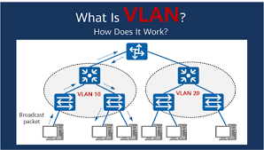
The following diagram shows the VLAN structure we are now be building.

Remember that while we can delete an IPv4 address simply by doing no ip address, we have to type in the entire IPv6 address to delete it (because IPv6 allows multiple addresses per interfaces, unlike IPv4).
On the Core Switch:
interface vlan 1
 no ip address
 no ipv6 address 2001:DB8:X:1::2/64
 shutdown
!
interface vlan 10
 description Management VLAN Building 1
 ip address 172.2X.10.1 255.255.255.0
 ipv6 address 2001:DB8:X:10::1/64
 load-interval 30
 no ip redirects
 no ip proxy-arp
 no shutdown
!
interface vlan 20
 description Management VLAN Building 2
 ip address 172.2X.20.1 255.255.255.0
 ipv6 address 2001:DB8:X:20::1/64
 load-interval 30
 no ip redirects
 no ip proxy-arp
 no shutdown
!
In Building 1:
interface vlan 1
 no ip address
 no ipv6 address 2001:DB8:X:1::N/64
 shutdown
!
interface vlan 10
 description Management VLAN Building 1
 ip address 172.2X.10.N 255.255.255.0
 ipv6 address 2001:DB8:X:10::N/64
 load-interval 30
 no ip redirects
 no ip proxy-arp
 no shutdown
!
In Building 2:
interface vlan 1
 no ip address
 no ipv6 address 2001:DB8:X:1::N/64
 shutdown
!
interface vlan 20
 description Management VLAN Building 2
 ip address 172.2X.20.N 255.255.255.0
 ipv6 address 2001:DB8:X:20::N/64
 load-interval 30
 no ip redirects
 no ip proxy-arp
 no shutdown
!
Replace N with the actual number used in the address.
Notice the sequence!!
NB: It is very important to remove all IP addresses (both IPv4 and IPv6) from VLAN 1 and shut VLAN 1 down before anything is configured on the new management VLANs (VLAN 10 or VLAN 20).
If you see entries like this:
mac-address-table static c42f.13fb.0000 interface GigabitEthernet0/0 vlan 20in the configuration, then the above sequence for moving the management VLAN from VLAN 1 has not been followed properly.
To fix, try shutting down the VLAN interface mentioned (VLAN 20 in the above example), delete the line by putting a no in front of the offending configuration, and then bringing the VLAN interface back up again. If that doesn’t work (the mac-address-table line is still there), try clear mac-address-table static or ask your lab instructor for help.
Verify connectivity between switches. Can you ping?
Note: changing Management VLANs is quite tricky to achieve by remotely accessing the switch – it is normally done by accessing the switch’s console port (like we are doing here in the lab). Cisco IOS requires VLAN 1 to be shutdown before any packets are moved on VLAN 10 or VLAN 20, so we can’t even use the trick of accessing the switch over IPv6 while the IPv4 address is being moved.
Designating Edge Switch Ports
Now that the STAFF and STUDENT VLANs have been created, we can designate 4 edge ports each for STAFF and STUDENT VLAN access on the edge switches only (example is for Building 1):
interface range Gi1/0-3
 description Access Port VLAN 11 STAFF
 switchport mode access
 switchport access vlan 11
 load-interval 30
!
interface range Gi2/0-3
 description Access Port VLAN 12 STUDENT
 switchport mode access
 switchport access vlan 12
 load-interval 30
!
Verify which ports are members or trunks of each vlan:
show vlan briefImagine that there are computers connected to the STAFF vlan. Would they be able to ping the switch? Explain your response.
Now run the commands:
show interface description
show interface status
What do you see?
This is why it is important to make sure all interfaces have a description line configured – the above diagnostic command lets any operator see at one easy glance which switch interfaces are used for which function.
Verifying Connectivity
Trying pinging from switch to switch within your building. Ping the management interface addresses.
Can you ping any of the switches in the other building in your campus? What happens?
- On modern Cisco switches (using IOS 15.0 onwards) the default is to use
dot1qencapsulation (rather than the Cisco proprietary ISL). But we include thedot1qcommand in the configuration to enforce our requirements – the other options areislandnegotiate(where the switch will negotiate trunk encapsulation with its neighbour.↩ - If doing this on a live network, removing the IP addressing and shutting down VLAN 1 will remove all Internet connectivity for all users connected to the switches – so this activity is best done when the network is unused, usually early in the mornings or at weekend, depending on when the campus is quietest.↩